In moving platforms such as cars and drones, the position and orientation of the sensors are determined with GNSS and IMU respectively. In this article, we explain how these techniques work.
In moving platforms such as cars and drones, the position and orientation of the sensors are determined with GNSS and IMU respectively. GNSS (Global Navigation Satellite System) is an umbrella term for satellite positioning. An IMU (Inertial Measurement Unit) operates without outside signals and is mainly used for determining the orientation of sensors.
Measurement principle
The oldest and best known GNSS is the American GPS. In addition, the Russian GLONASS, the European Galileo and the Chinese BeiDou are operational. When the positions of three satellites are known as well as the distances to them, the coordinates of the GNSS receiver's position can be calculated by intersection (Figure 1). In principle, but reality is unruly. Distances are not measured directly but calculated from the duration of the transmitted GNSS satellite signals: distance = duration x speed of light. The time of transmission is accurately recorded by stable, synchronized atomic clocks on board the satellites. It is impractical to install extremely expensive atomic clocks in GNSS receivers as well. Thus, not only the 3 coordinates are unknowns but also the clock error of the GNSS receiver. The correction is calculated with the signal of a fourth satellite.
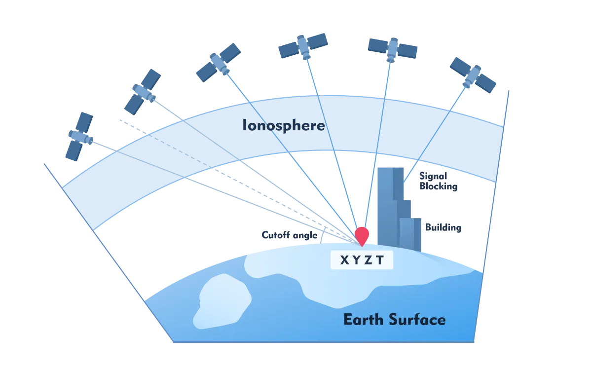
Figure 1 - Principle of GNSS positioning with some disturbances indicated, including blocking of GNSS signals by obstacles such as buildings. T is the correction for clock error.
GNSS constellation
The number of GNSS satellites varies by constellation and ranges from 22 to 35, orbiting the Earth in three (GLONASS) or six (other constellations) sophisticated orbits for optimal coverage. Most GNSS receivers process signals from multiple constellations, which contributes greatly to precision, reliability and operational reliability. The signals have multiple wavelengths and to receive all those signals requires hundreds of channels in the GNSS receiver. The satellites are continuously monitored from ground stations for determining their position, minute deviations from the atomic clock, etc. GNSS signals consist of a carrier wave containing codes that contain information about the satellite's position, time of transmission, etc. Without further facilities, the precision of code measurements is a few tens of meters. For many applications, this is insufficient.
Increase in GNSS accuracy
GNSS depends on signals from outside and is therefore sensitive to disturbances. For example, the atmosphere affects the run time. The disturbances are not constant because the atmosphere changes its composition locally constantly. The disturbances caused by the lower layer of the atmosphere - troposphere - can be compensated by using signals of different wavelengths: dual frequency. The disturbances from the upper layer - ionosphere - can be compensated by placing a GNSS receiver at a known point (base station). The difference between the measured position and known position is used to calculate the correction (Figure 2). With this technique - differential GNSS (DGNSS) - other disturbances can also be compensated. Governments and companies have created (nationwide) networks of such base stations that provide corrections to subscription holders.
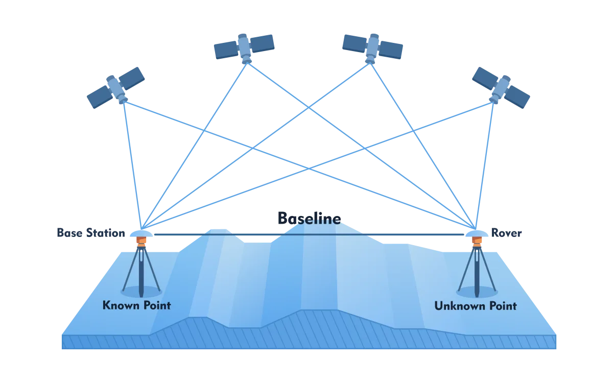
Figure 2- Principle of Differential GNSS (DGNSS), where one or more base stations are used to correct for atmospheric disturbances.
PDOP
Prevention is better than cure. The signals from satellites that are low on the horizon make a long journey through the atmosphere and are therefore highly susceptible to interference. Satellites lower than 15 degrees above the horizon are therefore not useful. If the satellites are very close together, even if there are a dozen of them, precision is poor. To assist the user, the combined effect of satellite geometry and the number of usable satellites on precision is condensed into one number: PDOP (Position Dilution of Precision). Survey precision requires PDOP values between one and three.
Not only the atmosphere but also the reflection properties of objects on the Earth's surface cause distortions. One source of error is multiple reflection (multipath) which also affects laser scanning (see also: Quality Aspects of Laser Scanning). The same GNSS signal reaches the receiver twice or more through multiple paths leading to inaccuracies in the calculation of X,Y,Z coordinates. This is especially true for stationary receivers in cities with many reflective surfaces (Figure 3). Mobile platforms are less affected by multipath.
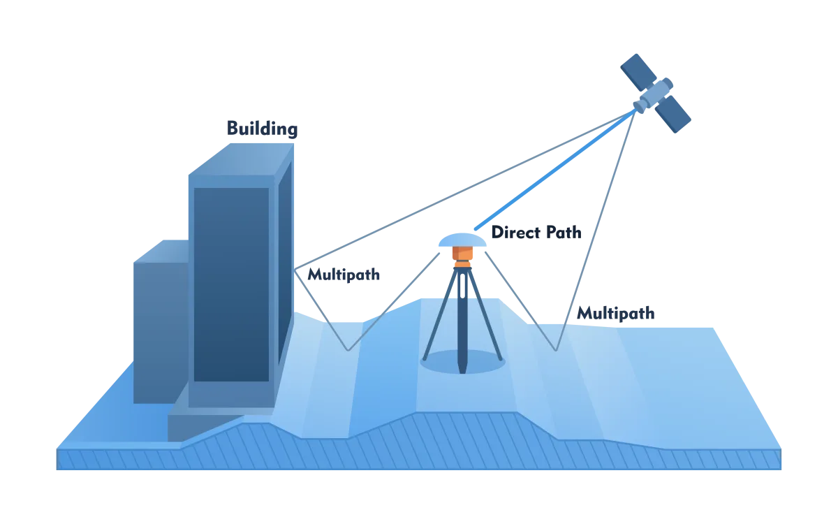
Figure 3 - Due to multiple reflections, a GNSS signal enters the receiver via multiple paths (multipath).
GNSS phase measurements
A particularly clever solution to increase accuracy is to use not only codes but also carrier waves. Carrier wave wavelengths are between two and three decimeters. The phase of the carrier wave can be measured to the millimeter. That does not mean that X,Y,Z coordinates can be calculated with millimeter precision. This is because of the distortions mentioned above. To get cm precision, a high-quality GNSS receiver requires measuring at the same point for several minutes or even several hours. With mobile platforms, this is not possible. Therefore, precision projects always require fitting points.
IMU
An IMU is required to determine the orientation of the sensor in space. This system operates autonomously, making it insensitive to outside disturbances. Three gyroscopes maintain its position in space no matter what movements the platform makes (Figure 4). This allows the three angles of orientation to be measured. Position can also be determined with the three orthogonally placed accelerometers. Integrating once over time provides velocity, and twice a distance. Once the initial position is known, the position can be determined from the distances and gyroscope angles. The drift of the accelerometers is large so that within just a few seconds to minutes the position no longer meets precision requirements. Miniaturization makes it possible to make the moving parts of an IMU so small that it fits in the palm of a hand or even between thumb and forefinger.
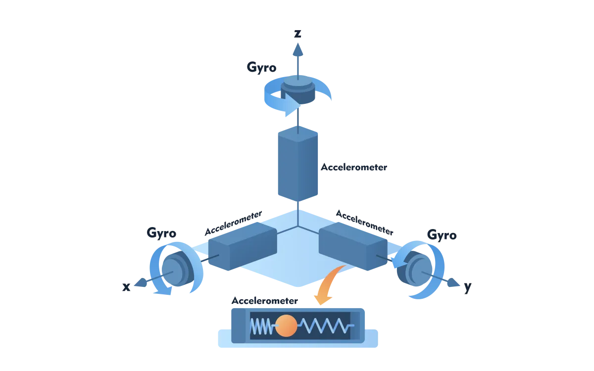
Figure 4 - Components of an IMU
GNSS/IMU integration
A golden rule in precision measurement is to measure more than is strictly necessary to calculate coordinates. Redundant measurements increase precision and can detect errors, such as multipath. The number of GNSS measurements is about ten per second, while IMU makes hundreds of measurements per second. The position between two measured GNSS positions can be determined by interpolation. When a platform is moving forward at 50 km/h, two measured GNSS positions are 1.4 m apart. To accurately determine the intermediate positions, the IMU can be used, as drift within a tenth of a second is negligible.
When a mobile platform travels through forest or city with high buildings, GNSS signals can be briefly blocked. GNSS/IMU integration makes it possible to bypass such blockages by using IMU positions as backups. GNSS and IMU are often combined into a single Position and Orientation (POS) system where measurements are combined via software.