Measurement in photographs - photogrammetry - is a field that originated around 1850 and has developed over time into an advanced measurement technology. This article describes the basics of this measurement technology.
Two types of information can be extracted from photographs: thematic information (what is there?) and geometric information (where is it?). Photogrammetry has specialized mainly in calculating 3-dimensional (3D) coordinates of object points (X,Y,Z) from 2-dimensional (2D) image coordinates (x,y). The photogrammetric measurement process consists of several steps partly related to the accuracy required for the project.
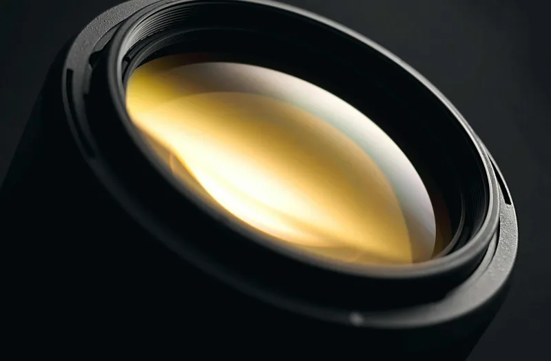
Measuring camera
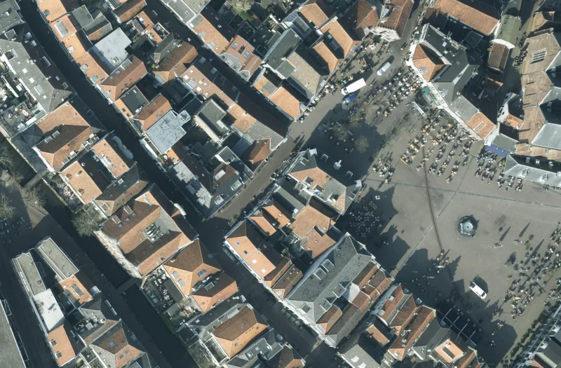
First, of course, photographs must be taken of the objects within the project. Photos are taken with one or more surveying cameras mounted on a platform, such as aircraft, drone, car and tripod. For most projects, photographs are taken from platforms that are in constant motion.
The mathematical description of a measurement camera consists of two components namely (Figure 1):
- Camera constant, called focal length in optics, i.e. the distance from the focal point of the lens (projection center) to the image sensor
- The coordinates of the point where the line through the projection center - optical axis - intersects the image sensor perpendicularly, called main point
All incident light rays pass through the projection center, which is realized by a system of lenses. The light rays are then projected onto the image sensor. In order to determine x,y coordinates of image points with a measuring instrument, a coordinate system must be defined for the image sensor. To convert the x,y coordinates to X,Y,Z object coordinates we use an important basic principle, namely that a point in object space (P), the image of that point on the image sensor (p) and the projection center lie on one straight line (collinearity). The camera constant (c) and the two main point coordinates (x0,y0), which together form the essential parameters of the camera, are accurately determined during a calibration process.
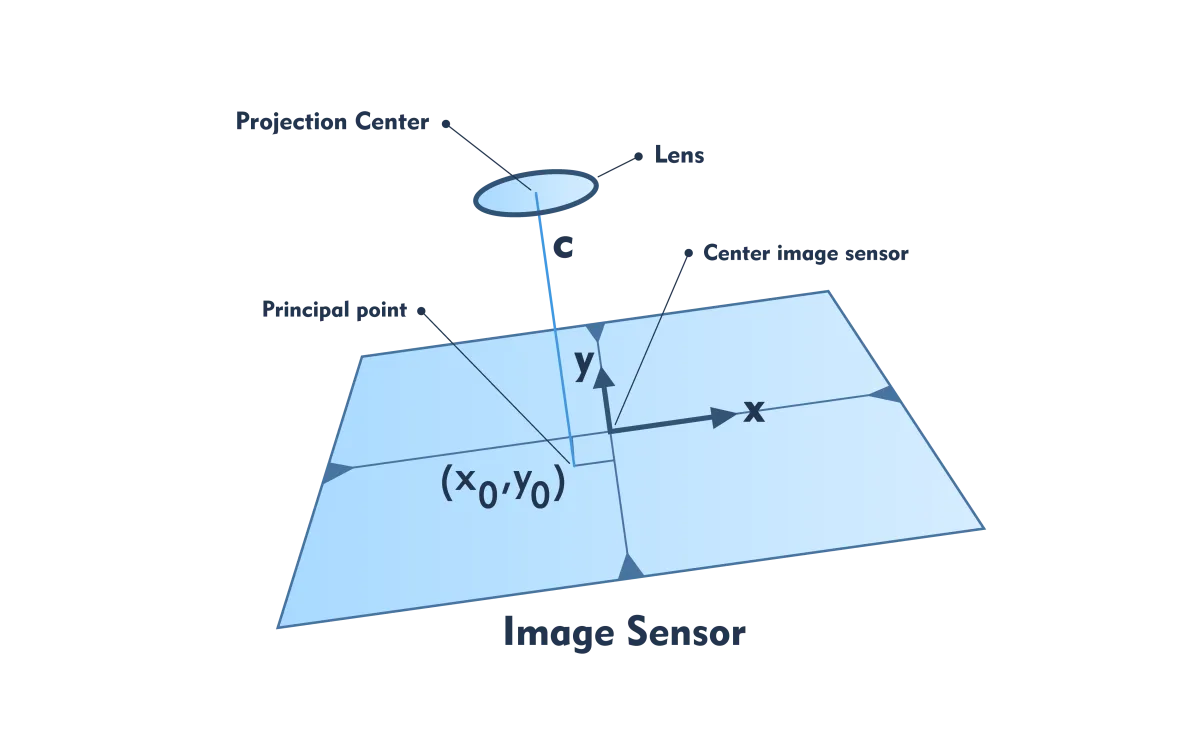
Figure 1 - Schematic of the essential components of a measurement camera: the camera constant (c) and the two main point coordinates (x0,y0)
Camera Position
To be of practical use, the X,Y,Z object coordinates of all points in the same coordinate system must have been determined. To do this, the position of the projection center and the position of the image sensor at the times the pictures are taken must be known in the chosen 3D coordinate system (Figure 2). The position of the projection center can be determined with a GNSS receiver placed next to the camera. The position of the image sensor - orientation - is described by three angles that can be measured with a gyroscope. Accelerometers are mounted on the three axes of the gyroscope. The combined system of gyroscope and accelerometers is called IMU (inertial measurement unit). In turn, GNSS receiver and IMU are usually integrated into one system called POS. The P stands for position and O for orientation. Some POS devices, as used in drones, fit in the palm of a hand.
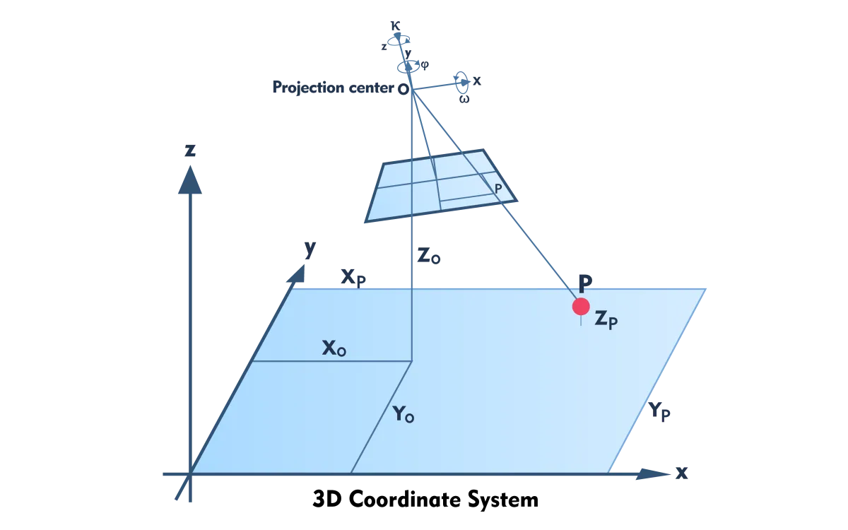
Figure 2 - Position of the projection center (X0,Y0,Z0) and orientation of the optical axis and thus of the image sensor (ω, ϕ, and κ; omega, phi, kappa) in the object space for which a 3D coordinate system is defined.
Pass Points
For many projects, such as the production of maps from aerial photographs, the accuracy of POS measurements is too low. To increase accuracy, an additional step is required where measurement experts place marks, which can be easily seen in the photographs, at sophisticated spots in the object space. The positions of these so-called pass points are measured with centimeter precision using high-quality and therefore expensive surveying equipment. In a complex computational process, the photographs are geometrically attached to these pass points. Sometimes POS measurements are included in this calculation process, but for projects that require very high precision, only pass points are used.
Overlapping Photos
According to the principle of collinearity, the x,y coordinates and the projection center determine the line on which the object point lies, but not where exactly the object point lies on that line. This requires a second image depicting the same part of the object space but from a different position and often different angle. The overlap between these stereo images is usually 60% to 80%. The corresponding points in the stereo pair are measured and the object point sought lies at the intersection of the two lines (Figure 3).
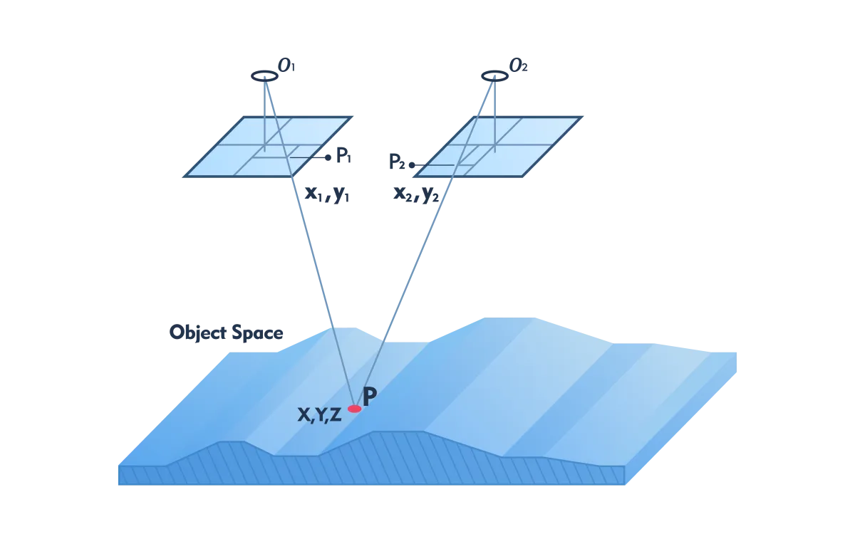
Figure 3 - p1 and p2 are the corresponding image points in two overlapping pictures of the same point P in object space.
In map-making, an operator manually measures the edges of objects in stereo images projected onto a computer screen. This measurement process very cleverly exploits the visual capacity of humans. When one image of a stereo pair is shown to the left eye and the other image to the right eye, both merge to form a 3D model. This allows the image coordinates of both points to be measured quickly and efficiently at the touch of a computer button. Point clouds, such as digital elevation models, which consist of a large collection of X,Y,Z coordinates, can be largely automatically acquired with image matching software. In these point clouds, also called 3D images, distances, areas, volumes and other information necessary for the project can then be measured. In addition to coordinates, thematic information, such as roads and buildings, is also collected when producing maps. This cannot be automated (yet). Therefore, an operator is needed.
Intake plan
When hundreds or thousands of photographs are needed to map objects or areas, it is necessary to create a thorough recording plan in advance. To ensure high-quality 3D information, the creation of the recording plan should be supported by simulation calculations.
Quality assurance
The final step is quality assurance. This step is important and indispensable. For here the question is answered whether the accuracy of all determined object coordinates meets the requirements set for the project. Photogrammetric quality assurance is a specialized job that requires great expertise.