Photogrammetry plays a crucial role in capturing and processing spatial information. The technology allows us to calculate highly accurate 3D models and coordinates from photographs and imagery. This is made possible by mathematical models and calculations. In this article, we pay attention to the camera model used in photogrammetry. This is the mathematical model used to describe the operation of the camera.
Photography and the camera obscura
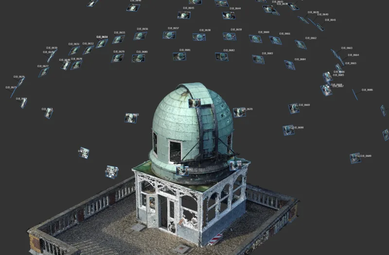
In photogrammetry, the environment is captured on photographic images by means of a camera. These can be regular cameras, or specially developed cameras. As long as the camera used meets some basic requirements, however, the choice of camera used makes no difference to the principles and calculations. Herein lies part of the charm of photogrammetry, it can be done both with expensive specialized equipment, and with inexpensive "off-the-shelf" components.
Understanding photogrammetric calculations first requires an analysis of how the camera works. The camera in its simplest form is the camera obscura, or darkroom. This is a completely darkened chamber with one small opening in one of the walls, as shown in Figure 1. The environment outside the darkroom is illuminated by natural or artificial light sources. The light reflects on the environment outside and some rays of light will reflect exactly in the direction of the small hole in the dark room. With that, the ray ends up on the back wall of the room. Thus creating an image on the back wall.
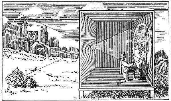
Figure 1 - Camera Obscura (Athanasius Kircher, Ars Magna Lucis Et Umbrae, 1645)
The camera obscura has some disadvantages in practice. For a sharp image, the hole in the wall should be as small as possible. With a larger hole, light rays from various directions will exit at the same spot. This results in a blurred image. However, a small hole also means that less light enters the room, so the image does not become sufficiently bright. This is solved by applying an objective lens. This is a composition of lenses that enlarges the opening in the wall while still allowing a sharp image to be obtained. From a photogrammetric perspective, the disadvantage of a camera with an objective lens is that it must be focused at a certain distance. The artistic photographer has actually embraced this effect, called depth-of-focus, as an art form.
Every modern photographic camera is still based on the principles of the darkroom. However, the hole has been replaced by an objective lens and the back by a light-sensitive sensor, such as a CCD or CMOS chip. The size of the darkroom can be very small. Think of a camera to be placed in a cell phone. The distance from hole to back wall is then at most a few millimeters. Analog photogrammetric cameras for aerial photography typically had a very large chamber, with the distance from hole to wall being about 30 centimeters.
We can formalize the camera obscura as in the diagram of Figure 2. The model is then called the pinhole camera model.
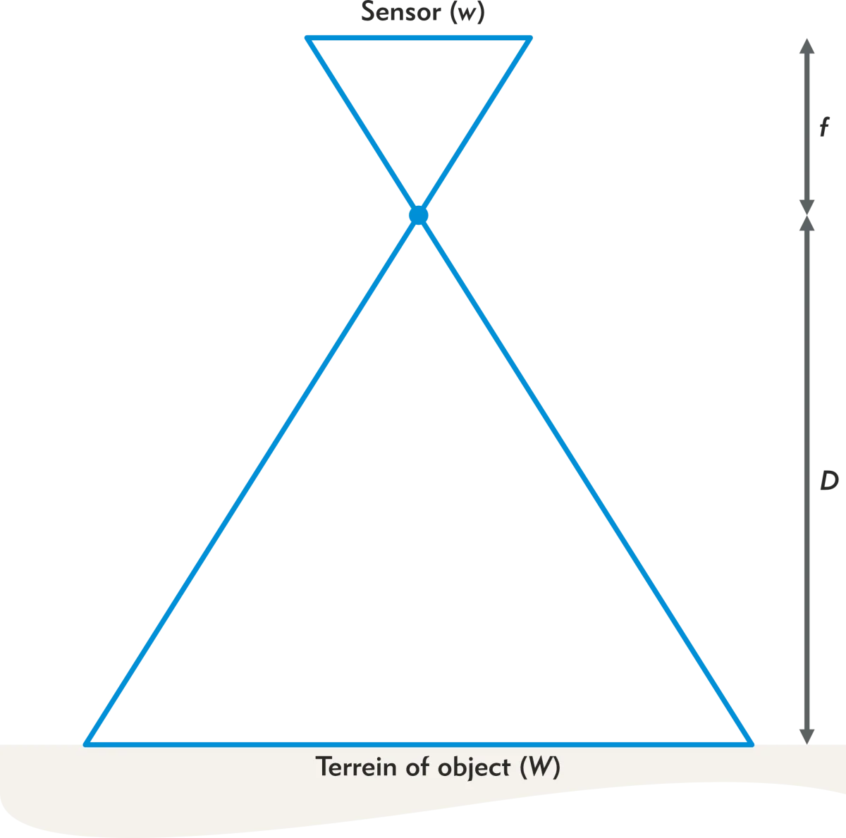
Figure 2 - Schematic representation of the pinhole camera
The pinhole through which the light passes is formally called the optical center. The back wall contains the light-sensitive sensor. In the era of analog photography with film rolls, it was also called the sensitive plate. We express the width of the sensor with the letter 𝑤. The dimensions of the sensor must be specified by the manufacturer. For example, digital SLRs for the consumer market often have a width of 24 mm (called APS-C).
The distance from the sensor to the aperture is called the focal length or camera constant . This distance is denoted by the letter 𝑓 or the letter 𝑐. The distance to the object is denoted by the letter 𝐷 for close-range photogrammetry, or in aerial photography with the letter 𝐻.
In the camera obscura image, it can be seen that the world is depicted "upside down." This is also true in the pinhole camera model. Each image is mirrored about the x-axis and the y-axis of the sensor. This corresponds to a 180-degree rotation. Camera manufacturers realize that most users prefer an image that is not upside down. The internal software therefore corrects directly for this mirroring (with sometimes additional processing, such as mirroring across the vertical axis for effective selfies). This corrected image is what we end up viewing in our photo album, on Instagram or in photogrammetric editing software.
We call the image on the sensor the negative plane. The corrected image we call the positive plane. Figure 3 shows the positive plane as a virtual line in the pinhole camera model. The point 𝑃 is depicted as 𝑝′ on the negative plane and as 𝑝 on the positive plane.
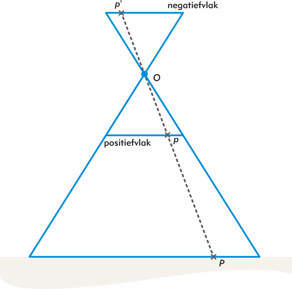
Figure 3 - Negative plane and Positive plane.
The central projection
The pinhole camera can be described mathematically as a central projection. The central projection is a projective transformation in which an N-dimensional space is imaged onto an (N-1)-dimensional subspace. Thus, in the case of photogrammetry, we image the three-dimensional space on a two-dimensional photograph. The central projection is a projective transformation involving a projection center. For each point in the terrain, a line can be drawn to the image of that point in the photograph. In the central projection, all these lines intersect at the projection center. In an ideal camera, the projection center coincides with the optical center.
Having shown that we can model photography as a central projection, it is possible to think of each photograph as a coordinate transformation from terrain system to photographic system. In close range photogrammetry, instead of the terrain system, the term object system is also used. The transformation can be notated at a high level of abstraction as follows:
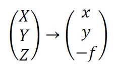
In this article, we adopt the convention that terrain coordinates are written in capital letters and photo coordinates as lower case. After all, terrain coordinates are usually also quite large, while photo coordinates and distances are much smaller. Usually, software also follows the convention that terrain coordinates are stored in meters and photo coordinates in millimeters.
The above transformation also shows immediately that there is a projection. Each coordinate receives the same z-coordinate, namely -𝑓, or focal length. Thus, we lose one dimension. The transformation from terrain system to photo system consists of rotation, translation and scaling. So we can write these as:
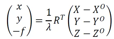
Herein, 𝜆 is the scale factor, 𝑅 is the rotation matrix and 𝑋𝑂, 𝑌𝑂 and 𝑍𝑂 are the location of the projection center in the terrain system. The rotation matrix can be defined as rotation from terrain system to photo system as well as rotation from photo system to terrain system. Unfortunately, there is no convention for this in the field and it remains a potential source of error and frustration in any project.
Collinearity and collinearity equations.
In the pinhole camera model, it was shown that light rays from the terrain reach the sensor via a straight line through the optical center. The central projection shows that this is true for every point imaged. This leads to an important observation that is the basis for all photogrammetric calculations:
A point 𝑃 in the terrain is always aligned with the projection center 𝑂, the image on the positive plane 𝑝 and the image on the negative plane 𝑝'.
This property is called collinearity. Of course, this is true only under the assumption that light rays actually follow a straight line. This is not always the case. Refraction, lens distortion and earth curvature mean that the assumption of a straight line does not always hold true. For now, we ignore these effects and turn on a model in which every ray of light follows a perfectly straight line. Upon turning off the model, we will have to assess whether this assumption was correct.
The collinearity follows from the central projection. We can write out the equation of the central projection as three independent equations:
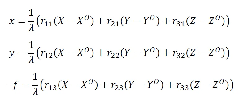
Herein, each 𝑟 represents the elements of the rotation matrix 𝑅. In practice, the scale factor 𝜆 of a picture is not known. However, by substituting, the three equations can be rewritten into two independent equations with no scale factor:
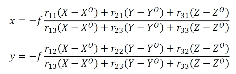
Note that the scale factor has now in fact been replaced by a factor that depends on the focal length 𝑓. The hobby photographer intuitively understands that this makes sense. When using a zoom lens, when he zooms in, he increases the value of 𝑓 and the subjects come closer. Thus, the scale becomes larger. When zooming out, the lens becomes shorter, so 𝑓 becomes smaller. There is then more in the picture, so the scale is smaller.
The above two equations are called the collinearity equations. They describe the relationship between objects in the terrain system, their image on the positive plane of the photograph, and the rotation and translation of the camera.
From camera model to coordinate determination
With the mathematical modeling of camera operation and the establishment of collinearity equations, the formulas are available to calculate three-dimensional coordinates from photographs. Part 2, the article Coordinate Determination describes how that works.