Photogrammetry plays a crucial role in capturing and processing spatial information. The technology allows us to calculate highly accurate 3D models and coordinates from photographs and imagery. This is made possible by mathematical models and calculations. In this article, we explain how coordinates can be determined from two or more photographs by pointing out corresponding points in the photographs.
Three-dimensional coordinates can be calculated from the overlap of two or more photographs. This requires first modeling the operation of the camera as a projective transformation. In the article Photogrammetry: The Camera Model, we explain how the camera model is defined. In it, we explain that we use a central projection. From this follow the collinearity equations that are the basis for all the calculations we perform in the photographs.
Forward intersection
The basis of coordinate determination is formed by the method of forward intersection. A principle that also has surveying applications, for example in measurements with a theodolite. Given the central projection, we know that a point we recognize in the terrain in a photograph must be aligned with the projection center and the point in the photograph. However, where the point lies on the line is unknown. One way to determine its location along the line is to look up the same point in another photograph. In that case, the intersection of the two lines defines the three-dimensional location of the terrain point (Figure 1). If the point can also be seen in other photographs, the reliability of the coordinate determination can be further increased.
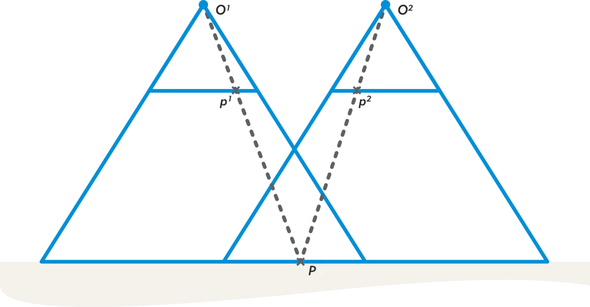
Figure 1 - The coordinates of a terrain point follows from the intersection of the lines passing through the center of projection of the photograph.
Determining the forward intersection from a minimum of two photographs requires that the position and position of the photograph be known. The orientation and position of the photo are described by 𝑋𝑂, 𝑌𝑂 and 𝑍𝑂 for the location of the projection center and the rotation matrix 𝑅 for the rotation of the photo system. Collectively, these parameters are called the external orientation .
That a minimum of two photos with known external orientation is necessary to determine a coordinate is also shown by the collinearity equations. With a measurement in one photograph, there are two observations (the 𝑥-coordinate and the 𝑦-coordinate), while there are three unknowns for the three-dimensional terrain coordinates of the point. By adding a second image, four observations are created with respect to the three unknowns. The redundancy is due to the fact that the two lines do not necessarily intersect in a single point. In reality, the two lines will often just barely intersect and we are looking for the location where the distance between the two lines is shortest. So an optimization problem that can be solved with least squares adjustment.
Photos with overlap
And so aerial photos are taken with overlap. During flight planning, the camera is set so that there is always sufficient overlap between photos so that three-dimensional coordinates can be calculated everywhere. In aerial photogrammetry, an overlap of 60% is usually chosen for standard stereo mapping (Figure 2). If point clouds are also to be calculated, an overlap of 80% is usually chosen.
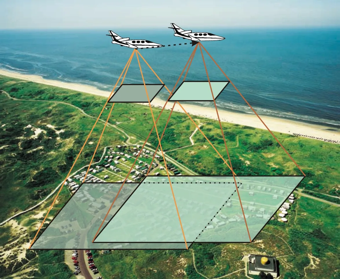
Figure 2 - A 60% overlap in aerial photogrammetry.
Where were the pictures taken?
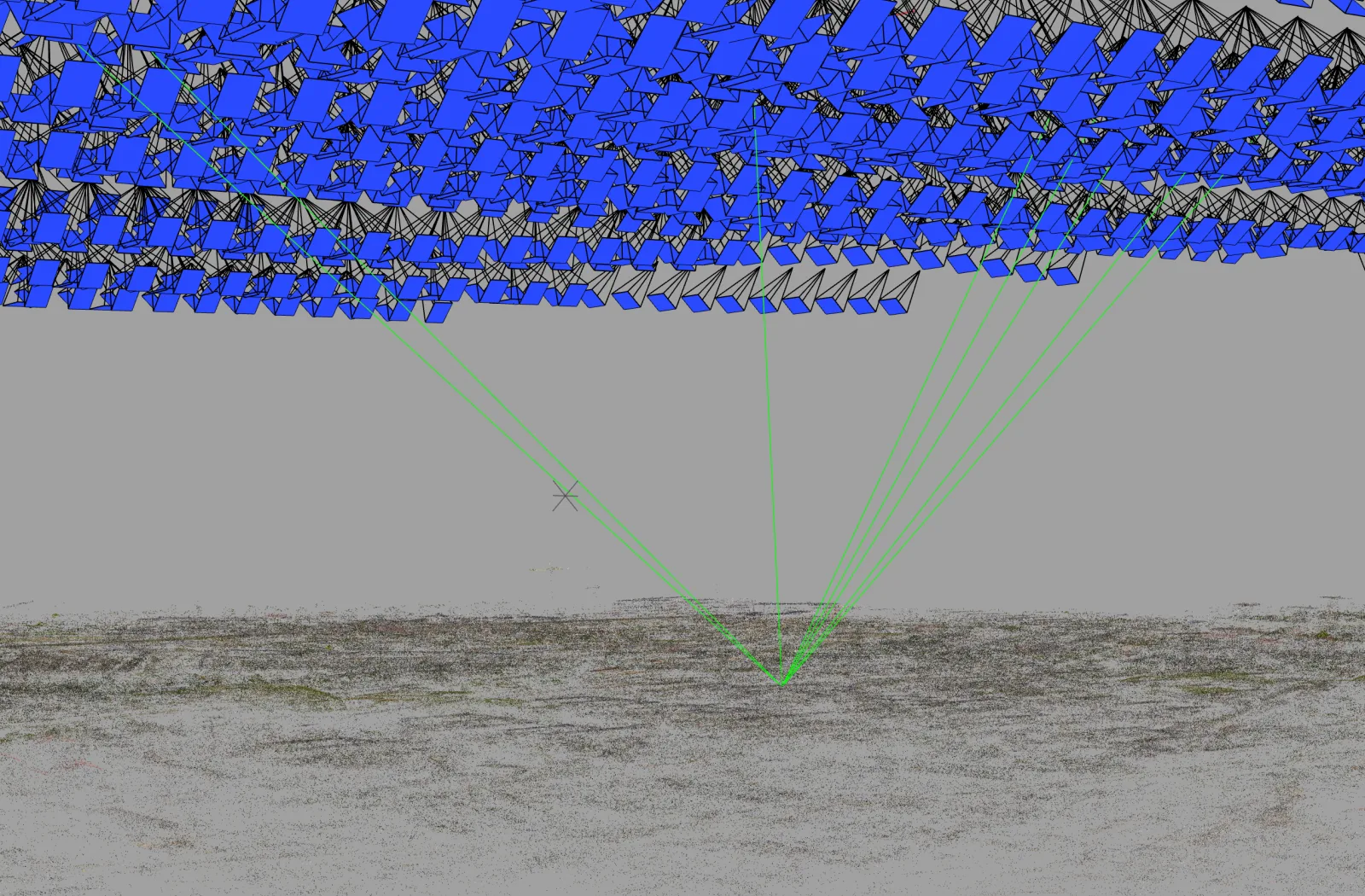
The method of calculating coordinates described here assumes that we know what the position of the photograph is in the terrain system. It also assumes that we know what the position of the camera was at the time of capture. In other words, what rotations apply to the photograph. Using GNSS and inertial navigation, the position and attitude can be measured. In practice, however, this is not sufficiently accurate. A better way to determine position and attitude is using triangulation and a bundle block adjustment. How this works is described in Section 3: Triangulation and bundle block adjustment.