Photogrammetry plays a crucial role in capturing and processing spatial information. The technology allows us to calculate highly accurate 3D models and coordinates from photographs and imagery. This is made possible by mathematical models and calculations. In this article, we explain how to calculate the attitude and position of photographs taken in an aircraft or drone.
Three-dimensional coordinates can be calculated from the overlap of two or more photographs. In the article Photogrammetry: Coordinate Determination, we explained how coordinates can be calculated from two photographs. For that to be possible, however, the position of both photos must be known. We also need to know what the position of both pictures was. We call this external orientation. The most reliable way to determine external orientation is with triangulation and bundle block adjustment.
Tie points
In practice, the external orientation of a photograph is not automatically known. It is possible to measure the external orientation while making the images, for example, through GNSS and INS observations. However, it is more accurate to calculate the external orientation.
It follows from the collinearity equations that three-dimensional coordinates can be determined if a point has been measured in at least two photographs (see Coordinate Determination). There are then four observations for three unknowns. In fact, a small least squares adjustment is used to perform this computation.
The external orientation per picture could be seen as an additional set of unknown parameters to be solved during such an adjustment. Measuring one point in two photographs is then no longer sufficient. There must always be more observations than unknowns. Would it be possible to determine external orientation by adding very many additional photo observations? This indeed turns out to be possible when applying the principle of bundle block adjustment.
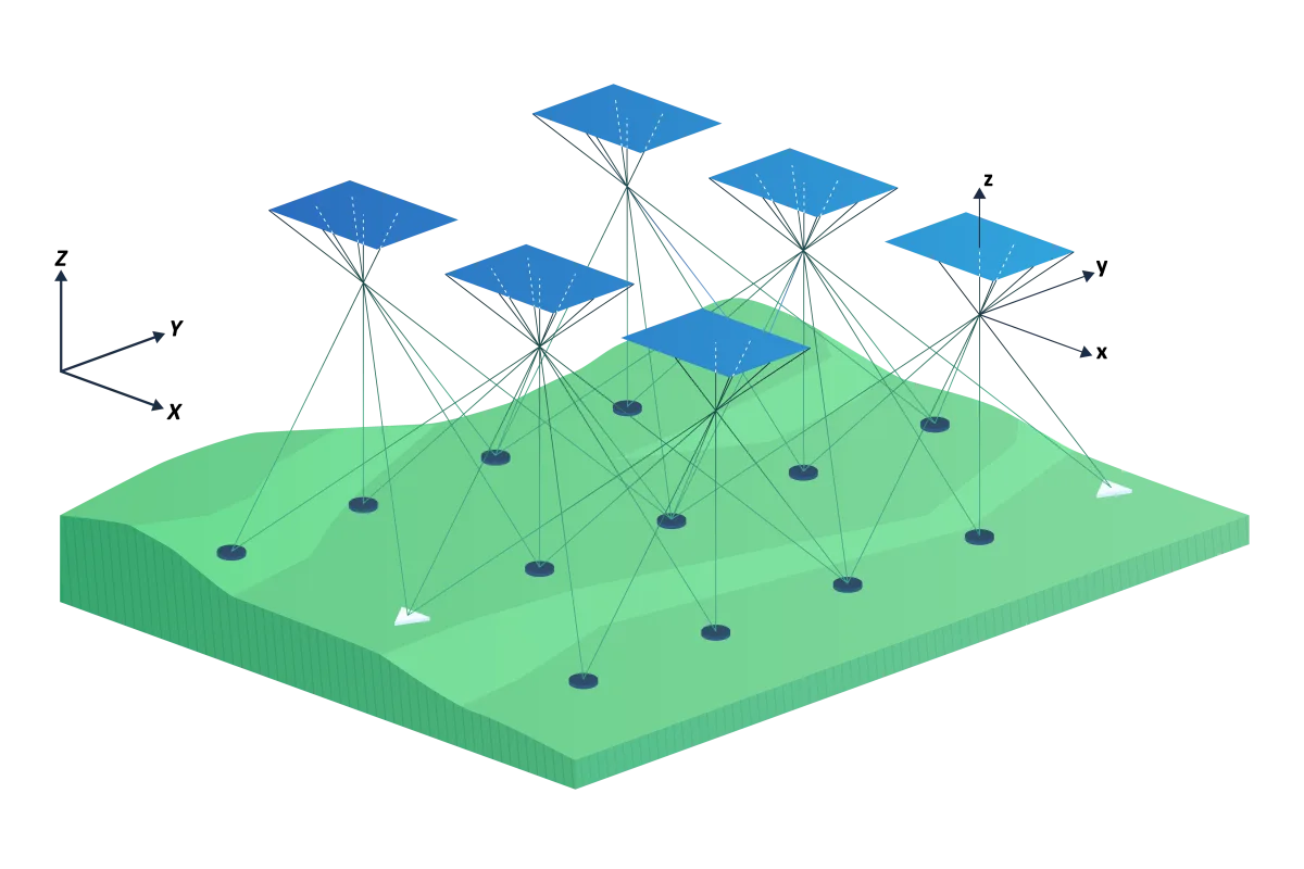
Figure 1 - Bundle block adjustment.
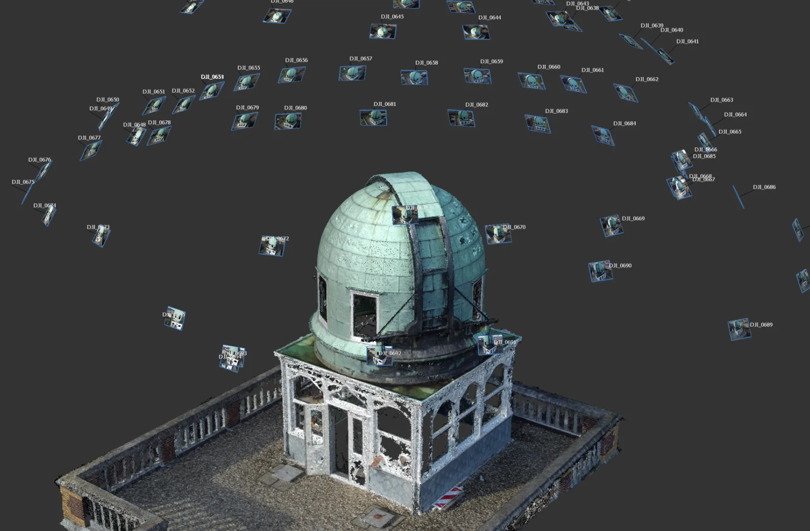
Figure 1 shows how a large number of points are measured in multiple photographs. These points are called tie points . The tie points are random points in the terrain. The meaning of the points is not important, as long as the points are easily identifiable and stable. Tie points can be measured manually. In this case, paint lines, curbs and other high-contrast objects are good candidates. However, many tie points are needed, so this is a lot of work. Tie points are therefore calculated fully automatically. Several algorithms are available for this, including SIFT and LightGlue. Both algorithms provide points that are meaningless to the human eye. For the algorithm, however, these points contain sufficient contrast characteristics to be found in multiple photographs. Figure 2 shows an example of some tie points between two oblique photos from a drone image. The process of determining and fitting tie points is called triangulation .
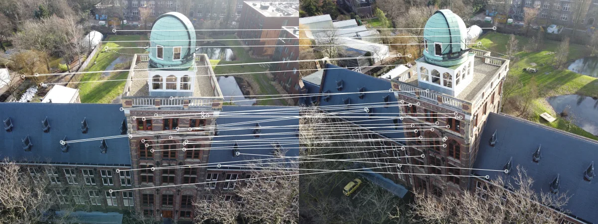
Figure 2 - Some tie points in two oblique images from a drone shot
Ground control points
Like any other surveying measurement, photogrammetry must be fitted to a coordinate system. A surveying measurement involves the use of a control network. This is a set of points that are recognizable in the terrain and whose coordinates are known. Photogrammetry also uses a ground control network consisting of a set of ground control points.
The ground control points are measured during triangulation in each photograph in which they are visible. A ground control point resembles a tie point in every way, except that for a tie point, the terrain coordinates are known. Ground control points are often clearly identified in the terrain by a white dot in a black circle (Figure 3). Close range and drone applications also employ signaling that can be automatically read by computer. For aerial photogrammetry, natural ground control points are also often used. These are points that are easily visible by themselves, such as paint lines and pits.
Sometimes check points are also applied in a project. These are points whose coordinates are known, but which are not used as ground control points. These points provide an independent check of the result achieved.
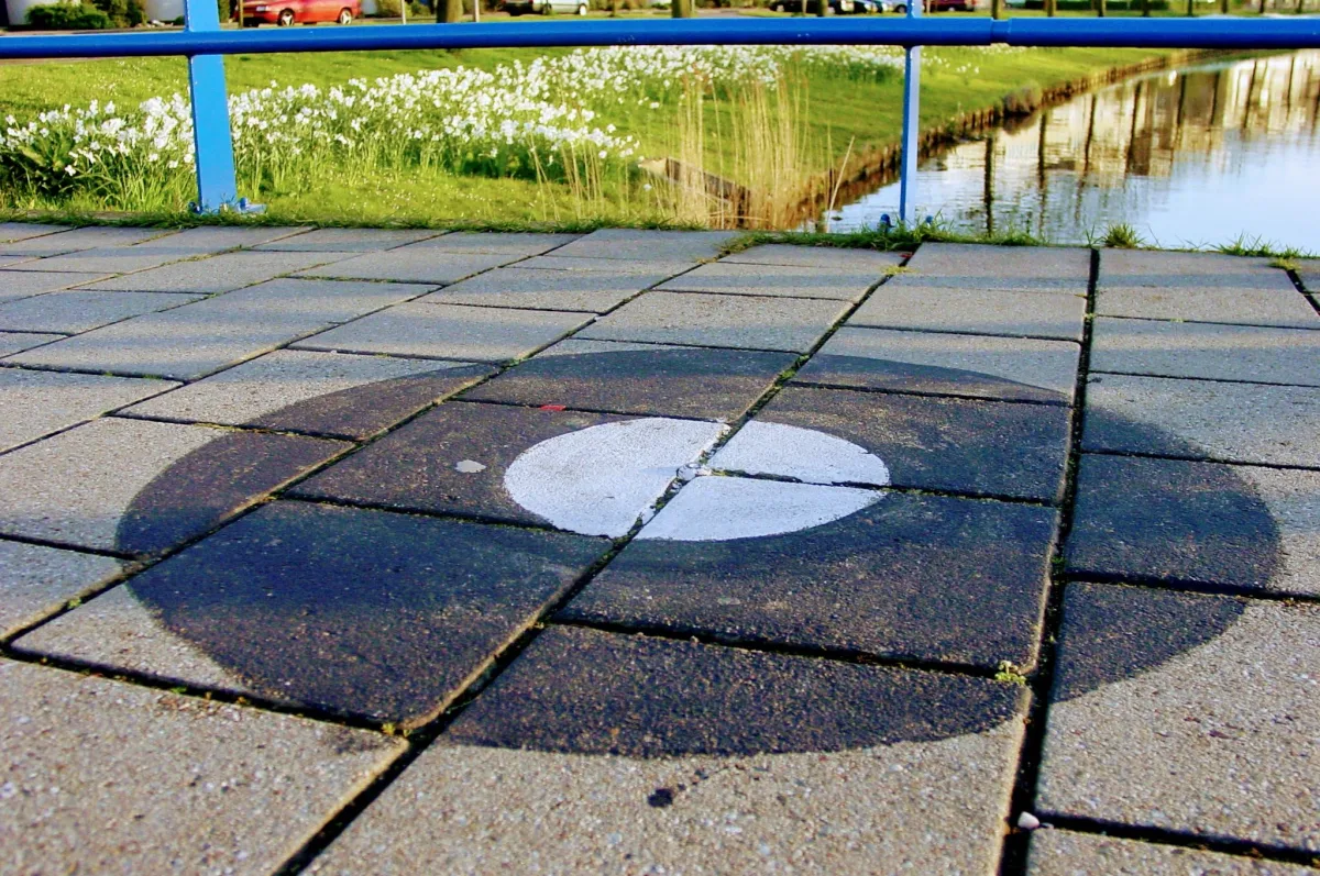
Figure 3 - A signalized ground control point for aerial photogrammetry.
Functional model for adjustment
From the picture in Figure 1, one can also intuitively see that this is a complex optimization problem. The collinearity condition continues to apply. As a result, for each photo observation, it is necessary that the point in the photo, the projection center and the point in the terrain be aligned. In addition, for ground control point observations, the terrain point must also carry the ground control point coordinates. To accomplish this, rotating and shifting the individual photographs is the only degree of freedom available. Here the practiced geodesist immediately sees the need for least squares adjustment.
The bundle block adjustment uses the A-model for adjustment based on observation equations. The collinearity equation is used for this purpose. The observations are the 𝑥- and 𝑦-coordinates of the tie points and ground control points in the photo system per terrain point per photo. In practice, for large blocks, these can be millions of observations. In addition, observations are added for the terrain coordinates of the ground control points and any GNSS/INS observations of camera attitude and position. The position and attitude of all images, as well as the terrain coordinates of the tie points, are the unknowns to be estimated with an adjustment. The bundle block adjustment is performed according to the Delft Method of adjustment and testing. As with surveying measurements, a full test for measurement errors as well as a quality description can then be reported.
Adjustment phases
In adjustments according to the Delft method of adjustment and testing, an adjustment is often performed in two stages:
- Free network adjustment: this tests whether measurement errors are present in the own observations. This step is of great importance. Tie points are automatically detected with an algorithm such as Sift or LightGlue, but it is not always flawless. Misconnected points can be detected in the first stage by testing (usually with the one-dimensional w-test) and then removed from the set of observations.
- Constrained adjustment: in this step the ground control points and GNSS/INS observations are added. Now that we have verified that all photo observations are correct, we can assume that any new errors that occur in this step are due to errors in our connection points. In the second stage adjustment, all photos are fitted into the desired coordinate system. The result of this adjustment is the final result of triangulation and bundle block adjustment.
From adjustment to finished product
With the determination of the external orientation of the photographs, it is possible to measure or calculate three-dimensional geometry from the photographs. The photographs can now be used directly for stereo mapping. It is also possible to calculate other products based on this information, such as point clouds using dense matching.
For applications requiring high quality, it is important to first properly test the end result of triangulation and bundle block adjustment. One aspect that requires special attention here is the calibration of the photo camera. Part 4 describes what is involved in the calibration of a camera for application in photogrammetry.